

Analyze an exported model before deciding whether it needs optimization. Counts and topology indicators help identify what to inspect, but they are not a pass/fail certification for every web application.
The current 3D Model Analyzer accepts GLB and FBX files up to 50 MB. This is a tool-specific limit; saved Dashboard models have a separate 100 MB limit. For glTF input, prepare an appropriate GLB export first.
1. Load a supported export
Open the 3D Model Analyzer and select or drop a GLB or FBX file within its current size limit. Wait for loading and analysis to finish, and review any reported error.
Analysis runs in the browser without an account or server processing. Keep the original asset unchanged so you can compare any later export with this baseline.
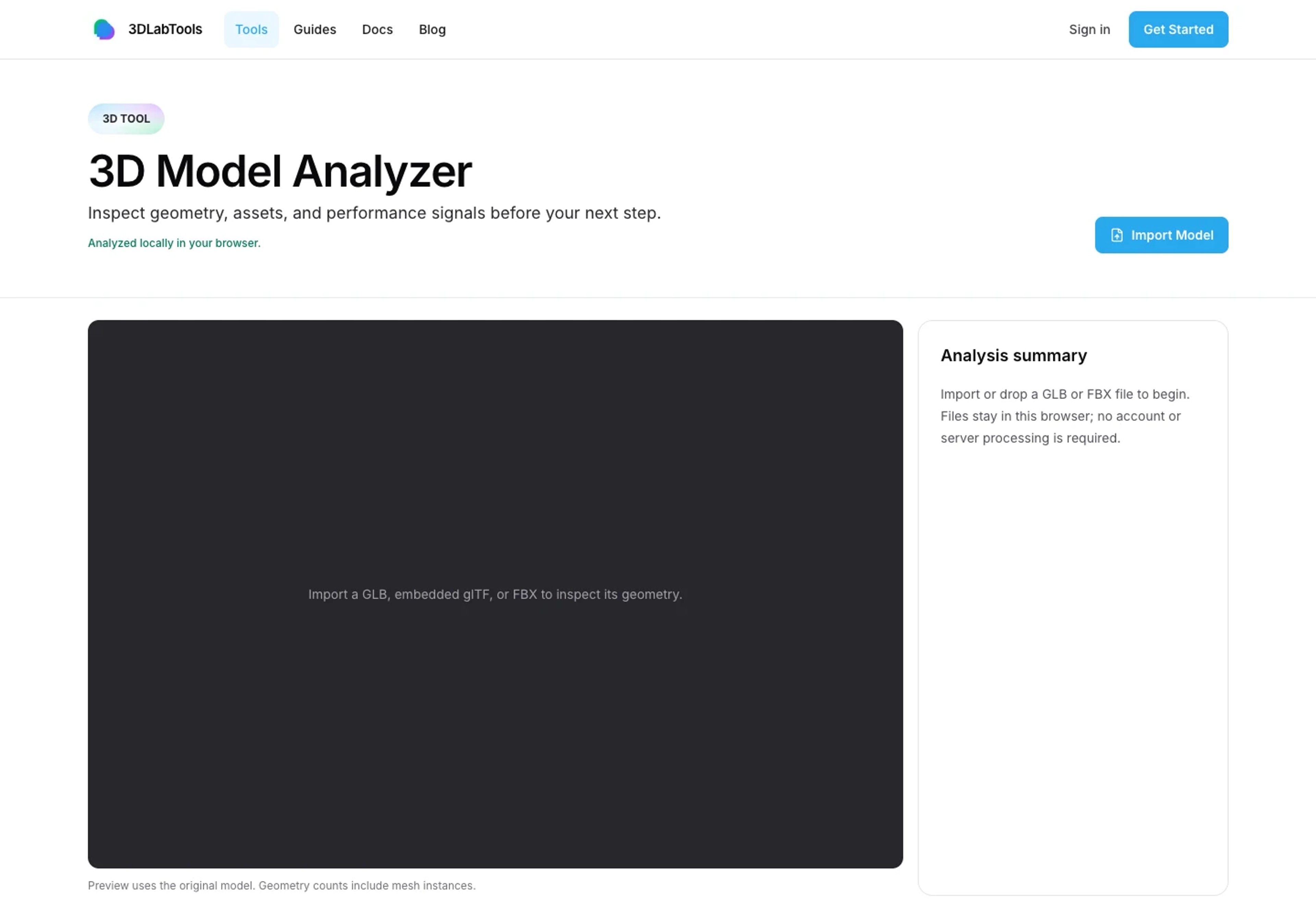
Load an export to inspect its structure. 2. Read triangles, vertices, and meshes together
Review the overview and geometry sections. Triangles describe rendered faces; vertices are the imported position entries, which can be split at UV or normal boundaries. Mesh and object counts describe scene organization, not just visible parts.
Counts include mesh instances in the analyzed scene. A higher vertex count does not automatically indicate a damaged model, and a low triangle count does not guarantee low overall rendering cost. Compare dimensions in model units with the intended export.
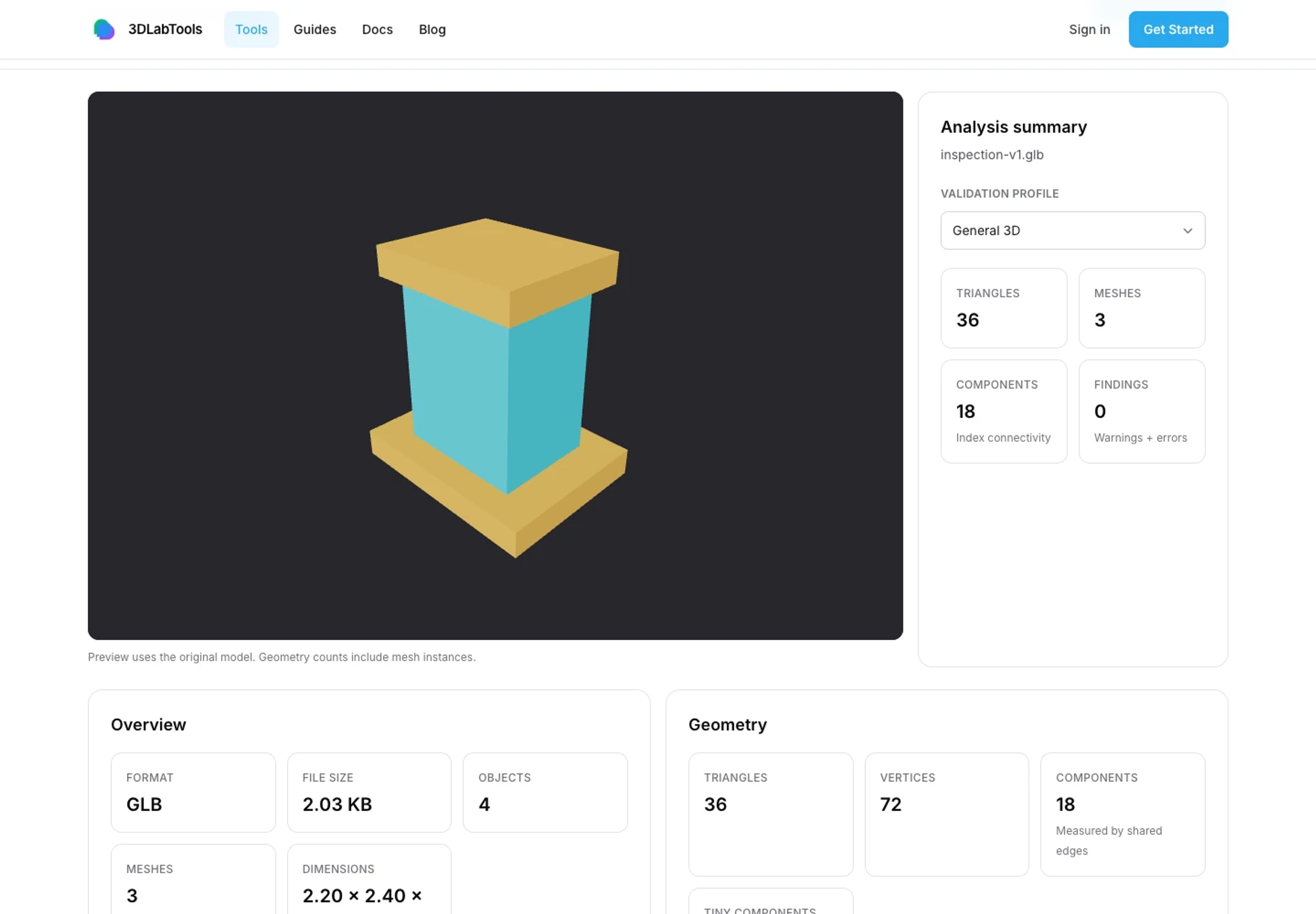
Read the model overview before deciding what to optimize. 3. Inspect materials and texture resources
Review material count, texture count, available texture dimensions, and estimated texture memory. A large texture can contribute significant runtime cost even when the file compresses well.
The draw-call figure is an estimate based on mesh groups, not a measurement of every frame in a destination renderer. Use it to identify a scene worth inspecting for many parts or material assignments, then check actual behavior in the Viewer.
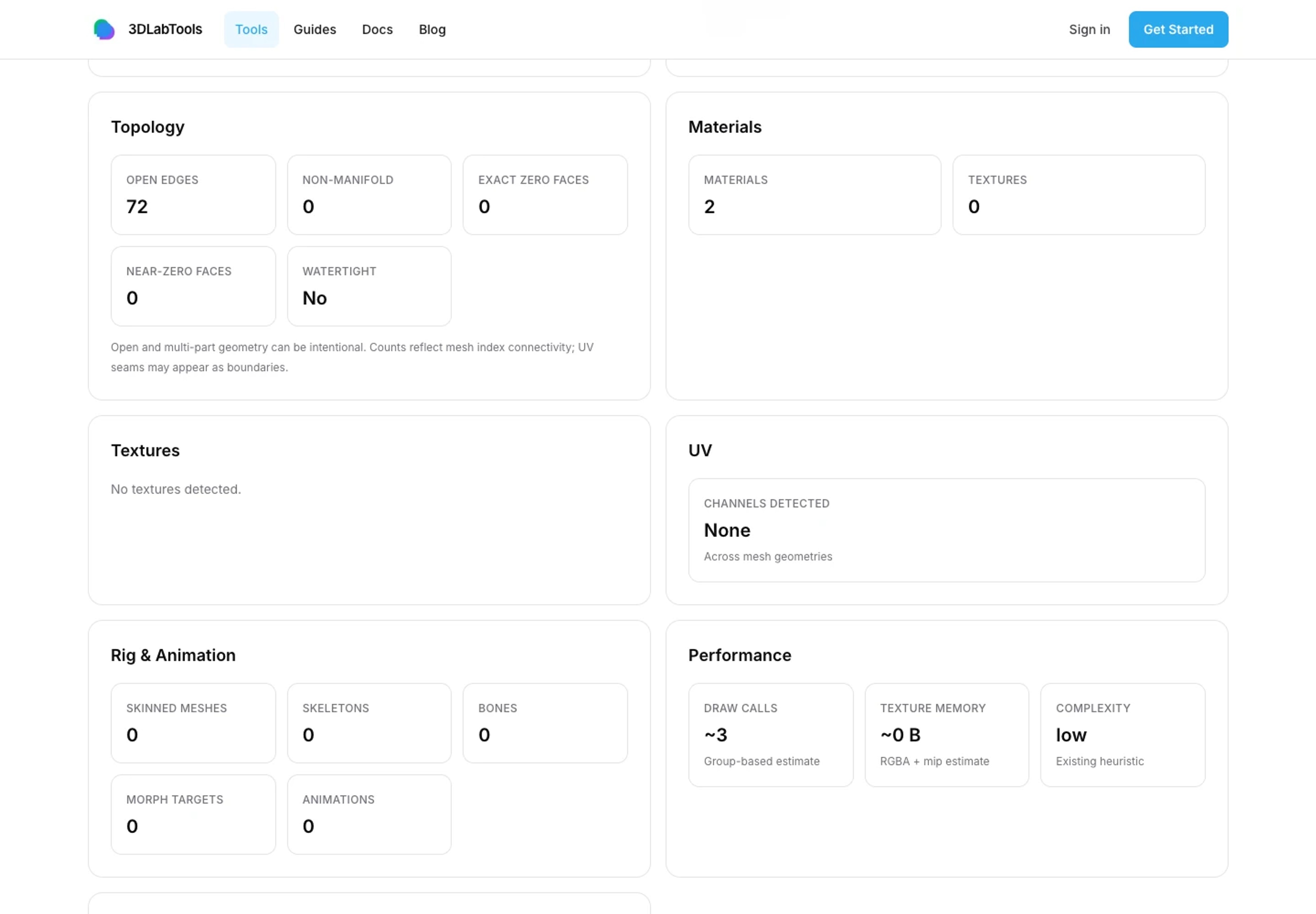
Check material and texture resources separately from geometry. 4. Interpret UV and topology indicators
Check which UV channels are present. A UV channel's presence does not prove that its layout, seams, or texture density meet your requirements; inspect the material appearance as well.
Review available open-edge, non-manifold, exact zero-face, near-zero-face, component, and watertight indicators. An open boundary can be intentional on a single-sided surface. Component counts follow the reported connectivity assumptions, and tiny components are a heuristic rather than an automatic deletion recommendation.
Some topology work can be limited or skipped for safety on heavy assets. If the tool reports that a result is unavailable, do not read that absence as zero problems.
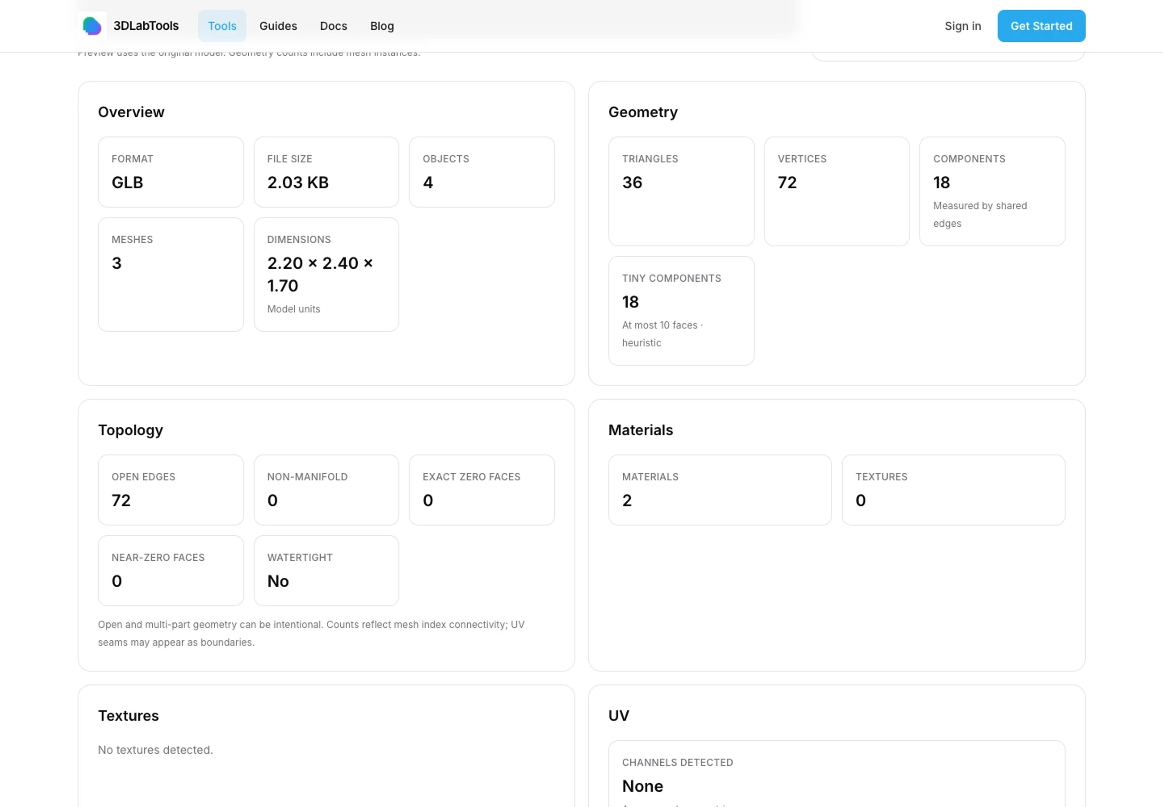
Use geometry statistics to identify areas worth inspecting. 5. Check animation and rig presence
Review the reported animation clips, skinned meshes, skeletons, bones, and morph targets. Presence indicates imported data, not correct deformation or compatibility with every engine.
Load the export in the Viewer and play important clips. For a rigged asset, inspect joint poses and material behavior before and after any geometry change.
6. Decide what to change, then recheck
Choose a change based on your use case: reduce invisible geometry, resize oversized textures, simplify unnecessary material assignments, or clean a specific topology issue in the source application. Make one controlled revision and compare both measurements and appearance.
Read How to Optimize 3D Models for the Web for a practical checklist. Auto Retopology is Experimental; treat any result as something to inspect, not an automatic production-ready fix. Finish by testing the model with the Viewer quality settings and browser/device class you intend to support.
Explore product documentation or open the 3D Viewer.